OFDMA
Evaluate a 5G MIMO uplink where multiple devices share the band.
How the workflow runs
Import the city geometry into Ansys Electronics Desktop. Choose base-station and user-device locations, and select antennas from the parametric dictionary or design arrays in HFSS.
Configure each source as a transmitter or receiver. Create a frequency sweep with a center frequency, bandwidth, and subcarrier count, then assign subcarriers and transmit powers to each transmitter.
Specify the noise power and which transmitters to decode, then calculate mutual information for linear and optimal decoding strategies.
Geometry
A three-sector base station uses one connected slot array per 120° sector — 16 elements backed by a PEC plate, designed at 5 GHz with half-wavelength spacing. The city is imported from OpenStreetMap at downtown Los Angeles, with buildings, roads, and terrain assigned as concrete. The four UEs use omnidirectional 2-element uniform linear arrays placed along the road — each UE-to-base-station link is a 2×16 MIMO system.
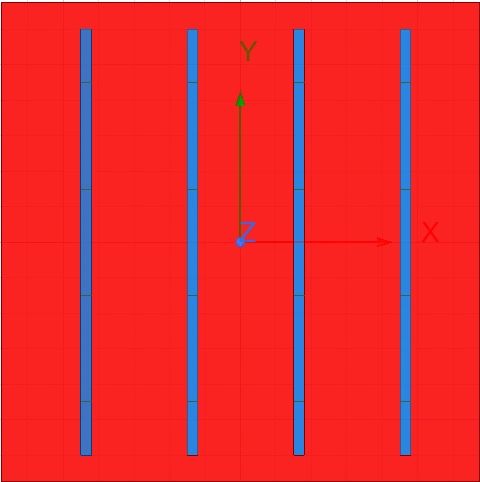
A 16-element connected slot array backed by a PEC plate forms one of the three base-station sectors.
Uplink System Configuration
The four UEs transmit to the base station using orthogonal frequency-division multiple access at 5 GHz over 100 MHz. Here, 10 subcarriers each get a dedicated 10 MHz: users 1 and 3 share the lower five subcarriers, users 2 and 4 the upper five.
Users 1 and 3 interfere over the first five subcarriers. The highlighted base-station sector was designed to connect both UEs to the cellular network.
Post-Processing
With the noise power and decoding targets specified, mutual information is computed for linear and optimal strategies.
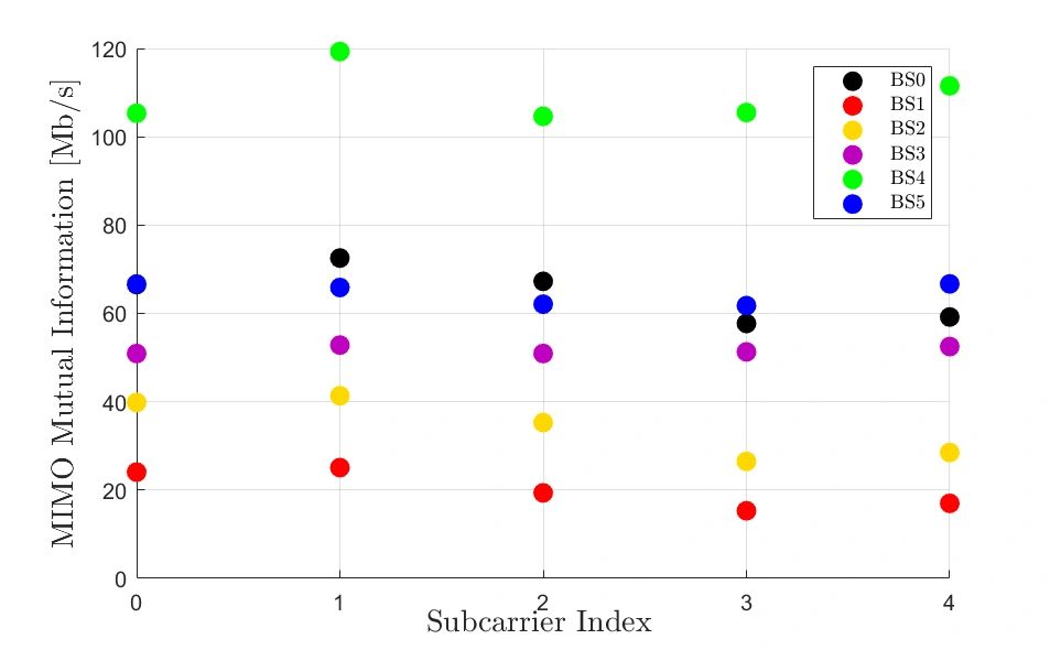
With −90 dBm noise at the base station and 100 mW per UE (50 mW per antenna), the MIMO capacity of user 3 is computed per subcarrier to every base station. Base station 4 gives the best connection — about 110 Mb/s per subcarrier, ≈11 bits per transmission (2048-QAM). Even with users interfering, optimal MIMO receiver processing mitigates the interference.
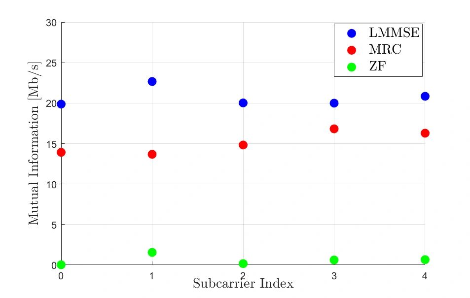
Connecting user 3 through base station 4, three linear detectors — MRC, ZF, and LMMSE — are compared against the achievable-rate limit. LMMSE performs best by exploiting the interference channel, but symbol-by-symbol decoding leaves a gap to the limit; ZF and MRC suffer under strong interference from user 1.
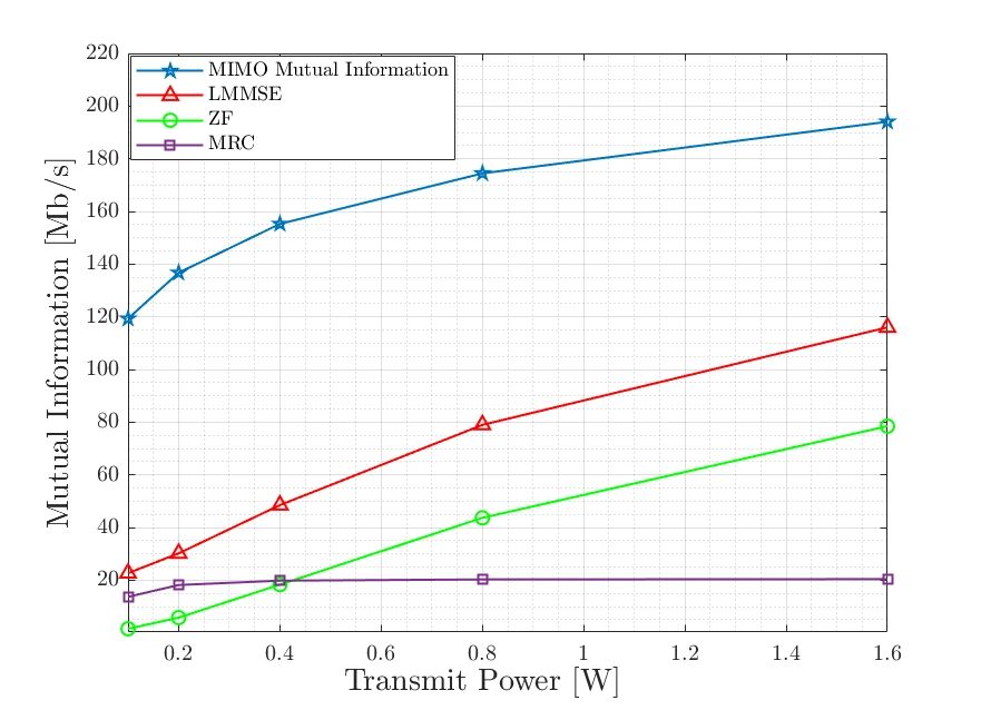
Plotted against transmit power, ZF trails MRC at low power and overtakes it at high power — in the noise-free limit ZF inverts the channel and matches LMMSE, while at low power MRC and LMMSE coincide.
Run this workflow on your geometry
WirelessAI agents set up and run this study on top of your Ansys Electronics Desktop environment — no Python required.