Multi-User MIMO
Test how well a base-station array separates co-channel users in space.
How the workflow runs
Import the city geometry into AEDT — here, part of downtown Los Angeles from OpenStreetMap. A single-sector base station uses a connected slot array backed by a PEC plate; the two users carry single omnidirectional Hertzian dipoles.
Configure all sources as transmitters or receivers and set a single 5 GHz frequency. The system is uplink — both dipoles transmit to the base station simultaneously.
Specify noise power and non-orthogonal transmission to form the channel and noise correlation matrices. Apply linear detection (uplink) or precoding (downlink) and compute per-UE SINR — here with −90 dBm noise and 0.5 W per UE.
Detectors
Three linear detectors separate the two co-channel users. Each bar graph shows per-user SINR after detection.
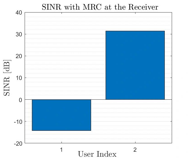
MRC multiplies the received vector by the conjugate transpose of the channel matrix, exploiting low correlation between user channels. Here the residual interference from user 2 sits ≈14 dB above user 1’s signal power — exposing MRC’s weakness as the simplest linear architecture.
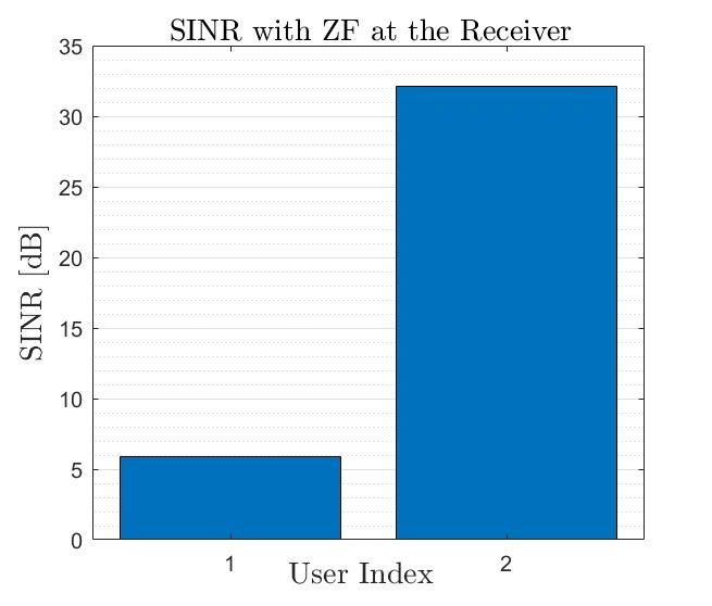
ZF applies the left pseudo-inverse of the channel matrix. User 1’s signal power lands ≈7 dB above the interference from user 2, so ZF separates the users in space with enough margin for space-division multiple access.
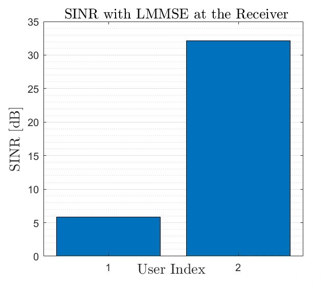
LMMSE forms a minimum-mean-squared-error estimate of the transmitted vector with purely linear operations, giving higher spatial resolution than MRC or ZF. At high SNR it reduces to ZF.
Run this workflow on your geometry
WirelessAI agents set up and run this study on top of your Ansys Electronics Desktop environment — no Python required.